bus bar in electrical is defined as a conductor or a group of conductor used for collecting electric power from the incoming feeders and distributes them to the outgoing feeders. The electrical bus bar is available in rectangular, cross-sectional, round and many other shapes. The rectangular bus bar is mostly used in the power system.
most common of the bus-bars size used-
- 40×4mm (160 mm2)
- 40×5 mm (200 mm2)
- 50×6 mm (300mm2)
- 60×8 mm (480 mm2)
- 80×8 (640 mm2)
- 100×10 mm (1000 mm2).
Bus Bar in Electrical–
The various types of busbar arrangement are used in the power system. The selection of the bus bar is depended on the different factor likes reliability, flexibility, cost etc. different type of electrical busbar arrangement is shown in below.
What is a Busbar in electrical-
A busbar is a metallic strip or bar that conducts electricity within a power distribution system. It is used to carry large amounts of electrical current efficiently, typically within switchgear, distribution boards, substations, or electrical panels. Busbars act as central hubs for power distribution, connecting various circuits and components without the need for complex wiring networks.
They are often made of copper or aluminum due to their excellent electrical conductivity, and they can be insulated or uninsulated depending on the application. Busbars come in various shapes—such as flat strips, solid bars, or hollow tubes—designed to manage current flow and heat dissipation effectively.
Types Of Bus – Bar Arrangements:-
Let us see each of bus – bar arrangements in detail now.
1. Single bus-bar arrangement–
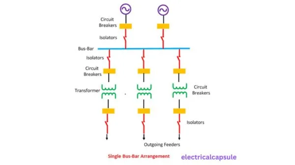
The system has only one bus bar along with the switch. All the substation equipment like the transformer, generator, the feeder is connected to this bus bar only. The single bus bar system has the simplest design and is used for power stations. It is also used in small outdoor stations having relatively few outgoing or incoming feeders and line.
advantages-
The chief advantages of this type of arrangement are low initial cost, less maintenance and simple operation
Disadvantages-
Single bus-bar system has the following three principal disadvantages :
(i) The bus-bar cannot be cleaned, repaired or tested without de-energising the whole system.
(ii) If a fault occurs on the bus-bar itself, there is complete interruption of supply.
(iii) Any fault on the system is fed by all the generating capacity, resulting in very large fault currents
Read also-
2. The single bus-bar arrangement with bus sectionalized-
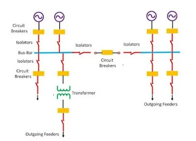
single bus-bar arrangement with bus sectionalized we divide a single bus – bar into two sections with the help of a circuit breaker and isolator switches and the load is distributed equally among both sections
advantages-
Three principal advantages are claimed for this arrangement.
Firstly, if a fault occurs on any section of the bus-bar, that section can be isolated without affecting the supply to other sections.
Secondly, if a fault occurs on any feeder, the fault current is much **lower than with unsectionalised bus-bar. This permits the use of circuit breakers of lower capacity in the feeders.
Thirdly, repairs and maintenance of any section of the bus-bar can be carried out by de-energising that section only, eliminating the possibility of complete shut-down.
Disadvantages–
- The system uses the additional circuit breaker and isolator which increases the cost of the system.
3-Duplicate bus-bar system-
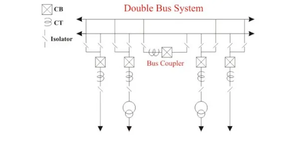
In large stations, it is important that breakdowns and maintenance should interfere as little as possible with continuity of supply. In order to achieve this objective, duplicate bus-bar system is used in important stations. Such a system consists of two bus-bars, a “main bus-bar’’ and a “spare” bus-bar. Each generator and feeder may be connected to either bus-bar with the help of bus coupler which consists of a circuit breaker and isolators.
Advantages–
(i) If repair and maintenance it to be carried on the main bus, the supply need not be interrupted as the entire load can be transferred to the spare bus.
(ii) The testing of feeder circuit breakers can be done by putting them on spare bus-bar, thus keeping the main bus-bar undisturbed.
(iii) If a fault occurs on the bus-bar, the continuity of supply to the circuit can be maintained by transferring it to the other bus-bar
4. Double bus double breaker arrangement-
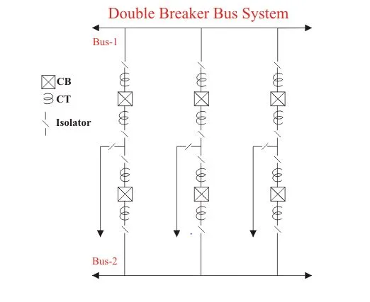
This scheme is seldom used expect in very large generating stations security and continuity of supply is of paramount importance. Advantages of this scheme are each circuit has two dedicated breakers and any breaker can be taken out of service for maintenance. Also the scheme has flexibility in permitting feeder circuits to be connected to either bus and is highly reliable.
Advantages-
1. During fault conditions, the load can be transferred to one bus so there will not be an interruption in power supply.
2. Here we are not using a bus coupler so there will not be much delay in power supply while closing circuit breaker to transfer load from one bus to another bus.
3. High flexibility.
Disadvantages-
1. The number of circuit breakers used is high so cost is very high.
2. Maintenance cost will also be high. So this type of arrangement is used very rarely.
5-Breaker and half scheme-
Breaker and a half scheme is and improvement of the double breaker schemes to affect the savings in the number of circuit breakers. For every two circuits only the spare breaker is used. The protection is complicated
since it must associated the central breaker with the feeders own feeder breaker taken out for maintenance. This scheme does not have much popularity because of the high cost of equipment.
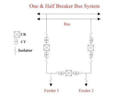
6-Mesh scheme-
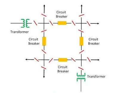
This scheme is also known as the ring scheme. This scheme has the following advantages
(1) It provides double feed to each circuit. Opening one breaker under maintenance does not affect the supply to any circuit
(2) It permits breaker maintenance
(3) All sections of the conductors in the station are covered by feeder protection and no separate bus protection is necessary
(4) Less costly than double bus or main and transfer bus scheme.
7-Main and transfer bus scheme-
The main and transfer bus scheme adds a transfer bus to the bus scheme. An extra bus-tie circuit breaker is provided to tie the main and transfer buses together.
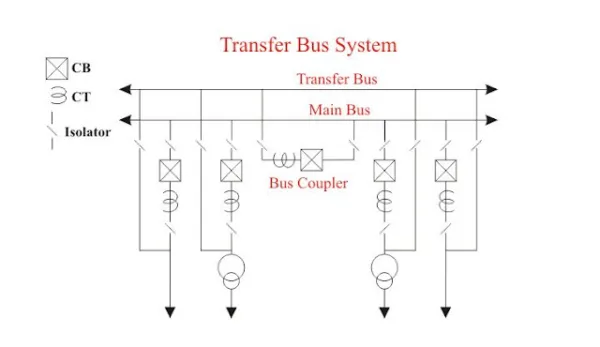
This scheme has disadvantages that this scheme requires one breaker for the bus tie. Again switching is some what complicated when maintaining a breaker and failure of bus or any circuit breaker results in shutdown of entire substation.
(All exam) multiple-choice questions (MCQs)–
1. Which busbar arrangement offers the highest reliability?
a) Single Bus Arrangement
b) Double Bus Single Breaker Arrangement
c) Main and Transfer Bus Arrangement
d) Ring Bus Arrangement
Answer: b) Double Bus Single Breaker Arrangement
2. In which arrangement is the cost minimized but reliability is low?
a) Single Bus Arrangement
b) One-and-a-Half Breaker Arrangement
c) Double Bus Double Breaker Arrangement
d) Ring Bus Arrangement
Answer: a) Single Bus Arrangement
3. What is the major disadvantage of a single bus arrangement?
a) Requires too many breakers
b) Low reliability due to lack of backup
c) High installation cost
d) Requires multiple transformers
Answer: b) Low reliability due to lack of backup
4. Which busbar arrangement is commonly used in large substations for flexibility and fault isolation?
a) Ring Bus Arrangement
b) Single Bus Arrangement
c) Main and Transfer Bus Arrangement
d) One-and-a-Half Breaker Arrangement
Answer: d) One-and-a-Half Breaker Arrangement
5. In which arrangement can a breaker be bypassed using a transfer bus?
a) Single Bus Arrangement
b) Main and Transfer Bus Arrangement
c) Ring Bus Arrangement
d) One-and-a-Half Breaker Arrangement
Answer: b) Main and Transfer Bus Arrangement
6. Which busbar arrangement is preferred for high-voltage substations?
a) One-and-a-Half Breaker Arrangement
b) Single Bus Arrangement
c) Double Bus Single Breaker Arrangement
d) Ring Bus Arrangement
Answer: a) One-and-a-Half Breaker Arrangement
7. Which busbar arrangement ensures continuous supply even if one breaker is under maintenance?
a) Main and Transfer Bus Arrangement
b) Single Bus Arrangement
c) Ring Bus Arrangement
d) One-and-a-Half Breaker Arrangement
Answer: c) Ring Bus Arrangement
8. In a double bus arrangement, what happens if one of the buses fails?
a) Entire system shuts down
b) Other bus takes over without interruption
c) Requires manual switching
d) Complete system isolation is necessary
Answer: b) Other bus takes over without interruption
9. Which of the following is a disadvantage of a ring bus arrangement?
a) Requires a large number of breakers
b) Complex operation
c) Limited flexibility in expansion
d) High cost of installation
Answer: c) Limited flexibility in expansion
10. What is the primary purpose of a transfer bus in a substation?
a) To transfer power between two substations
b) To allow maintenance of the main bus without disruption
c) To balance load among buses
d) To prevent overloading of transformers
Answer: b) To allow maintenance of the main bus without disruption
11. Which busbar arrangement uses two circuit breakers per circuit, enhancing reliability but increasing cost?
a) Double Bus Single Breaker Arrangement
b) Ring Bus Arrangement
c) Double Bus Double Breaker Arrangement
d) Single Bus Arrangement
Answer: c) Double Bus Double Breaker Arrangement
12. Which of the following busbar arrangements is most suitable for systems requiring easy expansion?
a) Single Bus Arrangement
b) One-and-a-Half Breaker Arrangement
c) Ring Bus Arrangement
d) Double Bus Double Breaker Arrangement
Answer: b) One-and-a-Half Breaker Arrangement
13. In a one-and-a-half breaker arrangement, how many circuit breakers are used for two circuits?
a) One
b) Two
c) Three
d) Four
Answer: c) Three
14. Which busbar arrangement ensures no loss of power supply during bus maintenance?
a) Main and Transfer Bus Arrangement
b) Single Bus Arrangement
c) Ring Bus Arrangement
d) Double Bus Single Breaker Arrangement
Answer: a) Main and Transfer Bus Arrangement
15. Which arrangement uses a continuous loop to connect multiple circuits?
a) One-and-a-Half Breaker Arrangement
b) Ring Bus Arrangement
c) Double Bus Double Breaker Arrangement
d) Single Bus Arrangement
Answer: b) Ring Bus Arrangement
16. What is the major limitation of a double bus single breaker arrangement?
a) High cost
b) Cannot isolate faults efficiently
c) Requires more space
d) Difficult to operate in emergencies
Answer: a) High cost
17. In which busbar arrangement are power circuits directly connected to a single bus?
a) Single Bus Arrangement
b) Main and Transfer Bus Arrangement
c) Ring Bus Arrangement
d) One-and-a-Half Breaker Arrangement
Answer: a) Single Bus Arrangement
18. Which type of busbar arrangement is often used in smaller substations due to simplicity and cost-effectiveness?
a) Single Bus Arrangement
b) Double Bus Single Breaker Arrangement
c) One-and-a-Half Breaker Arrangement
d) Main and Transfer Bus Arrangement
Answer: a) Single Bus Arrangement
19. What is the main benefit of a double bus double breaker arrangement?
a) Reduces installation cost
b) Provides the highest reliability and flexibility
c) Reduces space requirements
d) Requires only one breaker per circuit
Answer: b) Provides the highest reliability and flexibility
20. Which arrangement has each circuit connected between two buses in a way that breaking one bus does not interrupt the supply?
a) Ring Bus Arrangement
b) One-and-a-Half Breaker Arrangement
c) Double Bus Single Breaker Arrangement
d) Single Bus Arrangement
Answer: a) Ring Bus Arrangement
Where Are Busbars Used?
- Power distribution systems
- Electrical panels
- Industrial control systems
- Commercial and residential buildings
- Data centers and IT infrastructure
- Renewable energy systems
- Electrical substations
- Transportation systems
Exam MCQ-
- What type of busbar arrangement is used for high-voltage applications?
A) Air-Insulated Busbar
B) Gas-Insulated Busbar (GIS)
C) Cast-Resin Busbar
D) Flexible Busbar
Answer: B) Gas-Insulated Busbar (GIS)
- Which busbar arrangement is suitable for indoor applications?
A) Outdoor Busbar
B) Indoor Busbar
C) Air-Insulated Busbar
D) Cast-Resin Busbar
Answer: D) Cast-Resin Busbar
- What type of busbar arrangement is used for medium-voltage applications?
A) Air-Insulated Busbar
B) Gas-Insulated Busbar (GIS)
C) Cast-Resin Busbar
D) Oil-Immersed Busbar
Answer: C) Cast-Resin Busbar
- Which busbar arrangement provides flexibility in routing?
A) Rigid Busbar
B) Flexible Busbar
C) Air-Insulated Busbar
D) Gas-Insulated Busbar (GIS)
Answer: B) Flexible Busbar
- What type of busbar arrangement is used for low-voltage applications?
A) Air-Insulated Busbar
B) Gas-Insulated Busbar (GIS)
C) Cast-Resin Busbar
D) Insulated Busbar
Answer: D) Insulated Busbar
Types of Electrical Busbars–
Copper Busbars–
Copper is known for its superior conductivity and resistance to corrosion, making it a popular choice for high-performance busbars. However, its higher cost limits its usage in budget-sensitive applications.
Aluminum Busbars–
Although less conductive than copper, aluminum is much lighter and more affordable. It’s commonly used in applications where weight matters, such as electric vehicles and modular power systems.
Insulated vs. Bare Busbars–
Insulated busbars are covered with protective layers, which enhance safety by preventing accidental contact. Bare busbars are used in enclosed environments like switchgear and substations, where insulation isn’t necessary.
Advantages of Electrical Busbar Systems-
- Space Savings: Compact design, ideal for crowded electrical rooms.
- Improved Safety: Enclosed system reduces electrical shock and arc flash risks.
- Reduced Voltage Drop: Lower resistance minimizes voltage drop.
- Increased Reliability: Less prone to faults and failures.
- Flexibility: Easy expansion or modification.
- Low Maintenance: Minimal maintenance requirements.
- High Current-Carrying Capacity: Suitable for heavy-duty applications.
- Aesthetically Pleasing: Sleek, organized appearance.
- Cost-Effective: Reduced material and labor costs.
- Scalability: Easily scaled up or down.
Disadvantages of Electrical Busbar Systems-
- Higher Initial Cost: More expensive than traditional wiring.
- Complexity: Requires specialized knowledge for installation and maintenance.
- Limited Flexibility in Routing: Busbars have fixed routes.
- Difficult Troubleshooting: Enclosed system makes fault detection challenging.
- Specialized Tools Required: Customized tools for installation and maintenance.
- Limited Upgrade Options: Difficult to upgrade or replace components.
- Electromagnetic Interference (EMI): Potential for EMI issues.
- Thermal Expansion: Expansion and contraction can cause connection issues.
- Corrosion Risk: Moisture and contamination can cause corrosion.
- Standardization Issues: Lack of standardization across manufacturers.
Types of Busbars:-
- Rigid Busbars: Solid, rigid conductors used in electrical panels and distribution systems.
- Flexible Busbars: Flexible, insulated conductors used in applications requiring flexibility.
- Air-Insulated Busbars: Busbars with air insulation, used in high-voltage applications.
- Gas-Insulated Busbars (GIS): Busbars with gas insulation, used in high-voltage applications.
- Cast-Resin Busbars: Busbars with cast-resin insulation, used in medium-voltage applications.